MODBUS Communication between PLC and Delta VFD-V Series AC Motor Drive
PLC VFD MODBUS Communication Control Purpose:
Repeatedly reading the master frequency and output frequency of VFD-V series AC motor drive by MODRD instruction.
Setting the drive to run forward in 30Hz by MODRW instruction when X0 is pressed.
Setting the drive to run in reverse in 20Hz by MODRW instruction when X1 is pressed.
Stopping the drive by MODWR instruction when X2 is pressed.
MODBUS Parameter Settings for VFD-V Series AC Motor Drive:
Parameter
Set value
Explanation
00-20
1
Master frequency controlled by RS-485 communication.
00-21
0
Digital keypad (KPV-CE01)
09-00
01
Communication address: 01
09-01
9.6
Communication baud rate: 9600.
09-04
02
ASCII mode. Protocol: (7, E, 1).
· If AC motor drive cannot run normally due to improper parameters, users can set P00-02 = 10 (factory defaults) and then set the parameters according to the above table.
Devices:
Device
Function
X0
Forward
X1
Reverse
X2
Stop
M0
Executing MODRD instruction to read master and output frequency
M1
Executing MODWR instruction to set running direction and frequency
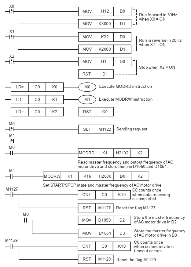
Modbus Communication between PLC and VFD Ladder Program:
MODBUS Communication PLC –VFD Program Description:
· Initialize PLC RS-485 communication port and set the communication format as MODBUS RTU, 19200, 8, N, 2. The RS-485 communication format of AC motor drive should be the same with PLC.
· Reset D0 and D1 when PLC is powered up so as to ensure the drive is in the Stop status
· When X0 is activated, the drive will run forward (D0 = H12) in 30Hz (D1 = 3000).
·When X1 is activated, the drive will run in reverse (D0 = H22) in 20Hz (D1 = K2000)
· When X2 is activated, the drive will stop. (D0 = H1, D1 = 0)
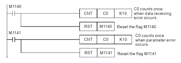
·There are only 4 situations for MODBUS communication: flag M1127 for normal communication and M1129, M1140, M1141 for communication errors. Counter C0 counts once when any of the 4 flags is ON. Therefore, the program assures the communication reliability by monitoring the On/Off status of the 4 flags and performs 2 MODBUS instructions in order by the value in counter C0.
·The master frequency and output frequency stored in D1050 and D1051 will be sent to D2 and D3.
·Once PLC starts running, the read/write actions for AC motor drive will be performed repeatedly according to [LD=] instructions.